Prototyping a handheld with the Omega2: A complete beginner’s guide
I wanted to build a handheld, WiFi-connected prototype as cheaply as I could. The Omega2 seemed like a great fit, but I’ve never worked with anything smaller than a laptop! For others looking to get into the prototyping of handheld mobile devices, I offer this beginner-friendly introduction to setting up the Omega2 and using it for a simple handheld device: a real-time clock display.

For this tutorial, I assume basic knowledge of the Linux command line, although I link to resources for beginners when those topics come up.
Why use the Omega2?
The Omega2 is a nice middle ground between the bare-bones microprocessor of the Arduino and the heavier OS of the Raspberry Pi. Like the Raspberry Pi, the Omega2 features a full-blown Linux operating system, which enables complex on-device computation. In terms of getting started quickly, the Omega2 has a built-in WiFi transmitter, which makes it perfect for a certain kind of project: Small, battery-powered mobile devices with built-in WiFi and a processor to do significant on-device computation.
Onion sells both an Omega2 and an Omega2+ chip. While I use the Omega2+, either will work fine for this tutorial. The biggest differences between the Omega2 and the Omega2+ are increased on-chip storage and RAM and the addition of an SD card slot for even greater storage needs.
Setting up the Omega2+
Initial setup of the Omega2 requires connecting it to a WiFi network in order to update the firmware and begin using its features.
If you’re trying to connect in a University or other environment with a login portal, you’ll need to bypass that portal. At the University of Minnesota, I was able to register the MAC address of the Omega2 directly with university IT, which bypasses the login portal.
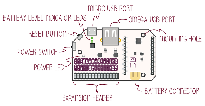
Use the switch on the side of the dock you’re using with the Omega2 to power on the device; you should see an orange LED on the Omega2.

Although the dock is powered by a USB connection, to connect to the device we have to use the Omega2’s own WiFi network. By default, this network is named “Omega-XXXX”, where the last four characters are the final four digits in the Omega2’s MAC address (labeled on the device). From my laptop, I connected to the Omega-5827 WiFi network, which usually showed up about a minute after powering up the Omega2. Then, I was able to access the Omega2 via SSH: ssh root@192.168.3.1
As soon as I was connected to the Omega2, I updated the password with the passwdcommand to change from the Omega2's defaults (username: root, password: onioneer).
The first step once connected is to update the Omega2’s firmware, which is handled by the oupgrade command. Because the firmware on my Omega2 was out-of-date, the automatic updater failed. I had to download and install the firmware manually, downloading the most recent Omega2 firmware images from here.
Connecting a battery to the Omega2 Power Dock
While the Omega2 can be powered with no dock, doing so is complex and unnecessary: Onion sells a variety of docks for the Omega2 that make powering the device easier. Since I wanted to create a mobile prototype, I used the Power Dock to connect easily to the Omega2 and to use an external battery.
Since I first ordered the Omega2’s Power Dock, Onion has released the Power Dock 2, which has a few advantages over the Power Dock. The most notable difference is the ability to programmatically access the remaining charge, which could be useful for a variety of reasons.
I spent $10 on a 3.7V LiPo battery, 1800 mAh, which shipped in two days (thanks Amazon!).
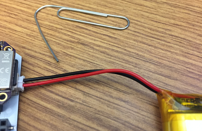
Others had warned that the configuration of the wires on the battery connector needs to be double-checked, since cheap LiPo batteries are often cheaply assembled. Indeed, the battery I received had the ends swapped in the 2-pin JST-PH connector; I used a paper clip to push down the metal flaps that lock in the power wires and swapped the two.
Once the pins were swapped, the power dock immediately started charging the battery. I never did a full rundown, but I got at least 4–6 hours of battery life while running the clock program we’ll build later in this tutorial. Switching to battery power is as easy as unplugging the USB cable from the dock; all power-switching happens completely automatically!
Connecting an SPI LCD to the Omega2
To demonstrate doing something useful with the Omega2, we’ll connect an LCD screen to display information. One of the cheapest options is to use an SPI-based LCD. SPI — Serial Peripheral Interface — is a communications protocol for all manner of input/output devices. Many LCDs implement the SPI protocol, which makes connecting them to the Omega2 easy, as the Omega2 has four digital pins that can also serve as SPI connections to a peripheral device.
While SPI defines the protocol for the sending and receiving of bytes between the Omega2 and an LCD, we still need to know which bytes to send. For this, we’ll need to know the driver used by the display and use a library on the Omega2 for communicating with that driver. I purchased a display that uses the ILI9225 driver.

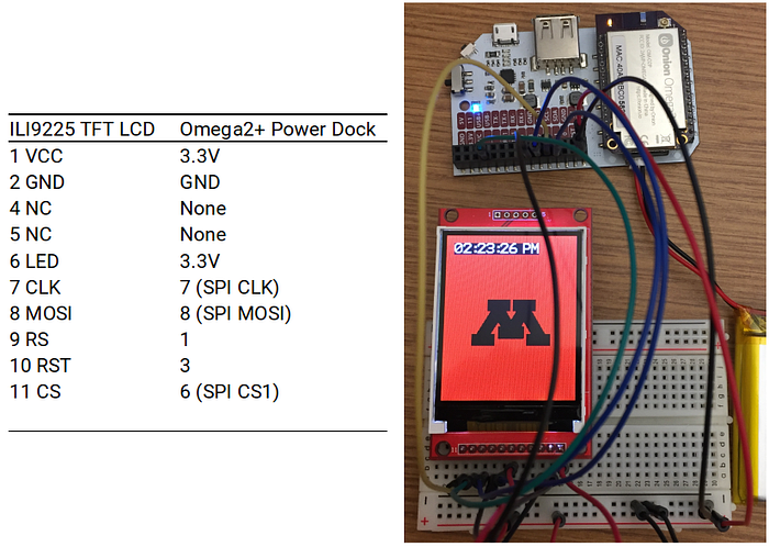
We’ll worry about the library we need on the Omega2 in the next section, but first let’s wire up this SPI LCD to our Omega2. The library we use lets us configure the pins that we’ll use on the Omega2 side to communicate with the LCD, but we need to make sure we wire to the correct pins on the LCD. To get the wiring correct, I relied heavily on this list of the LCD’s 11 pins and their descriptors so that I could map them appropriately to the Omega2 pins.
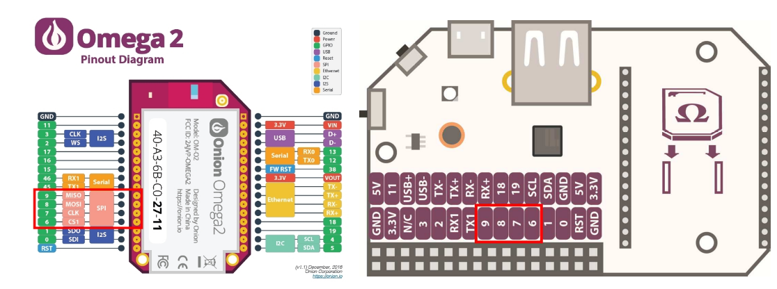
I first connected the LCD to a small breadboard, so that I wouldn’t have to do any soldering. Then, I used short wires to connect pins on the Omega2 Power Dock to rows on the breadboard corresponding to the LCD’s 11 pins. We connect from the LCD’s pins to the SPI pins MOSI, CLK, and CS1 — labeled 8, 7, and 6 on the Omega2 Power Board — as well as to a digital pin (in this case pin 1 on the Omega2).
From the Omega2 pinout diagram above, we can see that the SPI pin labeled “MISO” is unused in our wiring. Why? MISO stands for “Master Input, Slave Output”; it’s how the SPI device would send signals back to the “master” controller, the Omega2. But our SPI device is an LCD, so there’s no reason to receive any input!
I connected the LCD’s sixth pin — which powers the backlight — straight to the power. But you could connect it to another digital pin on the Omega2 if you wanted to modulate the brightness of the display.
Controlling an SPI LCD with the Omega2
Now that we have our SPI LCD screen wired to the Omega2, how can we control what is displayed on it? While the Omega2 offers lower-level options for sending packets of bytes to SPI devices, we want to use a library that makes it easy to tell the LCD “write some text” or “draw this rectangle”. Fortunately, a library was written for communicating with ILI9225-based displays. Unfortunately, it’ll take some setup to get this library working on the Omega2.
The library is written in C, and it needs to be compiled to the instruction set of the Omega2’s processor. Due to the large number of dependencies needed to do this compilation, Onion recommends building on a different computer and then transferring the compiled executable file to the Omega2. That means we’ll have to cross-compile from our computer’s processor to the Omega2’s processor. Why do we need to do this? Because the Omega2 has a MIPS processor — rather than the more common x86 or ARM processors. This means that a lot of software and drivers that were written for other processors won’t work nicely with the Omega2!
To set up cross-compiling on your computer, Onion provides a Docker image and better instructions for setting it up than I can provide here. Warning: Compiling the Omega2 build system can take several hours even on a decent system and things may still go wrong if you’re not using Docker on a Linux operating system! The build took about an hour on my Ubuntu desktop.
Once the build completed, I followed the instructions in the ILI9225 library to produce a demo executable. In addition to using the Docker setup, I found this info on configuring paths for cross-compiling to be essential for creating the right environment for a successful build.
I set up Git on the Omega2 directly and used it to transfer the built executable to the Omega2. I ran the executable (./displayDemo) from my SSH session and was greeted with this:
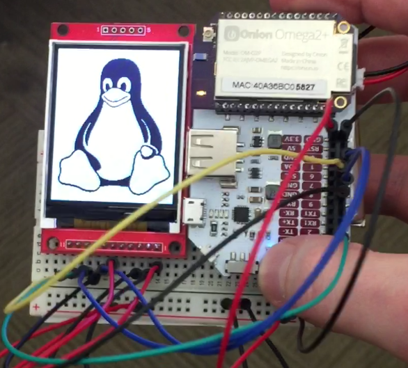
Success! We have a working build system for the ILI9225 library, and we can now use it to write C code to display custom content.
Coding a clock display
Now, let’s extend the ILI9225 SPI library with our own code to display something a little more complex: a bitmap of our choosing and a live time display. We’ll use the SPI library we got working in the last section to write our own display code, but first we need to do two things: (1) set the timezone on our Omega2 so the time shown is accurate and (2) get the bitmap image we want to display.
We can set the timezone for the Omega2 by editing the /var/TZ file on the Omega2. By default, the timezone is GMT0, but I consulted this list of timezones to update to US Central time.
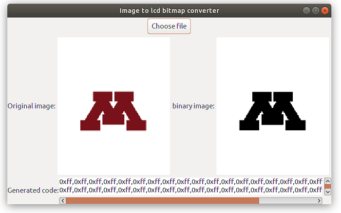
The ILI9225 SPI library doesn’t have a built-in utility for displaying generic images, but it can display bitmap images represented as arrays. Loading a bitmap as the appropriate array of bytes seemed beyond me, but fortunately Adafruit provides a nice utility for converting images into the uint8_t bitmap arrays the SPI library expects. I chose the University of Minnesota logo.
I built my code on the example provided with the SPI library.
I assigned the generated bitmap code to an array const uint8_t ili9225_umnlogo_img[], then used the SPI library’s commands to display it:
ILI9225_ClearFramebuffer();
ILI9225_SetBackgroundColor(COLOR_BLACK);
ILI9225_DrawBitmap(0,0,ili9225_umnlogo_img,180,220,COLOR_RED);
ILI9225_CopyFramebuffer();
The last thing to do is to write a few lines of C code to display the time every second or so:
while (1) {
  // Get the current time
  time_t rawtime;
  time ( &rawtime );
  struct tm * timeinfo = localtime ( &rawtime );

  // Format the current time as a string
  char time_buf [20];
  strftime(time_buf, 20, "%I:%M:%S %p", timeinfo);  // Draw the text using the SPI library
  ILI9225_DrawText2(10, 10, &time_buf[0]);
  ILI9225_CopyFramebuffer();

  // Sleep between refreshes
  usleep(1000 * 1000);
 }
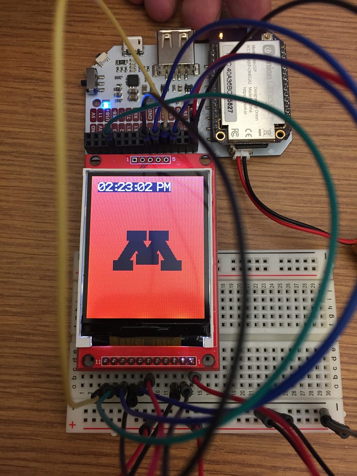
And that’s all we need to finish the code for our prototype!
Compiling the C code into an executable is a bit of a beast:
mipsel-openwrt-linux-gcc -o displayTime -O3 -ggdb -g -Wall -Wextra -I /root/source/staging_dir/target-mipsel_24kc_musl-1.1.16/usr/include -I /root/omega2-libs/omega_includes -L /root/source/staging_dir/target-mipsel_24kc_musl-1.1.16/usr/lib -L /root/omega2-libs/omega_libs -L. ili9225_lcd_demo.c -lili9225 -loniondebug -lonionspi -lugpioFortunately, the build command was generated for me by the sample Makefile in the ILI9225 library. This Makefile serves as a nice template to build on. I transferred the binary produced by the build to the Omega2 and confirmed everything was working as expected. I’m not building any kind of case for this tutorial, but I did use a cable tie to make a quick-and-dirty handheld.
Wrapping Up
I was thrilled to get a simple battery-powered prototype working, but there’s so much more we could do!
One obvious step is making a small box to contain the components and to make this prototype durable enough for a user study. Laser cutting is a good option: I plan to make a box out of one of these materials.
The breadboard is great for rapid prototyping and the quick addition and subtraction of I/O peripherals, but it would also be reasonable to solder some of the connections to make a more durable item.
We could also write more complex code that makes use of the built-in WiFi connection, which is one of big benefits of using the Omega2 for a prototype. A concrete next project could be adding input buttons and packaging the Omega2 into the same form factor as the original Gameboy as an extension to this awesome Omega2 project. Play original Gameboy games on the go for less than $40!
Hat tip to Maximilian Gerhardt for providing code and useful sample projects; without Max’s forum posts, it wouldn’t be possible for a beginner like me to wade into this space and set up a functioning ILI9225 display with the Omega2.